

Table of Contents
- What is mmWave Antenna Testing?
- Why Are Anechoic Chambers Important for mmWave Testing?
- How mmWave Antenna Testing Works in an Anechoic Chambers?
- Industries That Rely on mmWave Anechoic Chamber Testing
Millimeter wave technology is reshaping wireless communication, automotive radar, satellite links, and
advanced sensing systems. As frequencies move higher into the mmWave range, antenna design and validation
become much more demanding. Even small alignment issues, reflections, cable losses, or environmental
interference can distort results and lead to misleading performance data. That is why mmWave antenna testing
using anechoic chambers has become a standard practice for engineers and manufacturers
who need reliable, repeatable measurements.
What Is mmWave Antenna Testing?
mmWave antenna testing refers to the measurement and validation of antennas operating in the millimeter
wave spectrum, typically from 24 GHz to 100 GHz and beyond, depending on the application. These antennas
are used in technologies such as 5G, 6G research, automotive radar, fixed wireless access, satellite
communication, and high-resolution imaging.
Unlike lower-frequency antenna testing, mmWave measurements are more sensitive to:
- path loss
- connector and cable losses
- alignment tolerances
- material imperfections
- reflections from nearby objects
- temperature and mechanical stability
Because of these challenges, engineers often prefer over-the-air (OTA) testing in highly controlled
environments rather than relying only on traditional conducted measurements.
Why Anechoic Chambers Are Used for mmWave Testing
An anechoic chamber is a specially designed room lined with RF-absorbing material that minimizes signal
reflections. It creates an environment that closely simulates free-space conditions. This is critical
for antenna testing because reflections from walls, ceilings, floors, and nearby equipment can alter the
measured radiation pattern.
For mmWave frequencies, the need for an anechoic chamber becomes even greater because:
1. Shorter wavelengths are more easily disrupted
At mmWave frequencies, very small objects or surface irregularities can affect signal propagation.
2. Beamforming antennas require precise measurement
Many mmWave systems use phased arrays and beam steering. These systems need accurate chamber-based
testing to verify beam direction, sidelobes, and gain.
3. OTA testing is often mandatory
Integrated mmWave devices often combine antennas and RF front-end circuits so tightly that direct
connector-based testing is limited or impossible.
4. Repeatability matters
Product development, compliance testing, and design optimization all require repeatable results.
Anechoic chambers help remove environmental uncertainty.
Key Parameters Measured in mmWave Antenna Testing
Engineers use anechoic chambers to capture a range of antenna performance metrics. Each parameter helps
determine whether the antenna will perform as expected in real-world deployment.
Common mmWave Antenna Test Parameters
| Parameter | What It Measures | Why It Matters |
|---|---|---|
| Gain | Antenna power concentration in a given direction | Indicates signal strength and link quality |
| Radiation Pattern | How energy is distributed in space | Reveals main lobe, sidelobes, and nulls |
| Beamwidth | Angular width of the main radiation lobe | Affects coverage and targeting precision |
| Efficiency | Ratio of radiated power to input power | Shows how much power is effectively transmitted |
| Polarization | Orientation of the electromagnetic field | Important for signal matching and system compatibility |
| Return Loss / VSWR | Impedance matching performance | Helps identify mismatch and power reflection |
| EIRP | Effective isotropic radiated power | Essential for compliance and system-level evaluation |
| Beam Steering Accuracy | Correctness of beam direction in phased arrays | Critical for 5G and radar systems |
These measurements are often performed through automated positioners and precision instrumentation to
ensure high resolution and minimal human error.
How mmWave Antenna Testing Works in an Anechoic Chambers
The basic setup includes the antenna under test, a reference antenna or probe, RF instrumentation,
positioners, and chamber absorbers. Depending on the antenna size and frequency, the test may be done in
the near field or far field.
Typical testing workflow:
- The antenna is mounted on a non-reflective fixture.
- The chamber is calibrated using reference standards.
- The antenna is aligned with extreme precision.
- Measurements are taken across frequencies and angles.
- Software processes the captured data into gain plots, 3D patterns, and efficiency calculations.
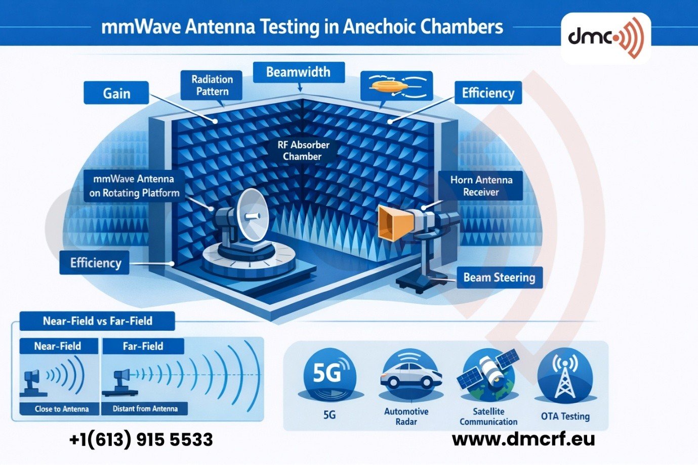
Near-Field vs Far-Field Testing
Two common methods are used in mmWave antenna chambers: near-field testing and far-field testing.
Near-field testing
Near-field systems measure electromagnetic fields close to the antenna and then mathematically transform
the data into far-field patterns. This approach is useful when the chamber size is limited or when very
high-resolution scans are needed.
Far-field testing
Far-field testing measures the radiation pattern at a distance where the wavefront is considered planar.
This method is conceptually simpler but may require a longer chamber, especially for larger antennas.
Here is a simple comparison:
| Test Method | Best For | Main Advantage | Main Limitation |
|---|---|---|---|
| Near-Field | Compact chambers, detailed scans, large antennas | Space efficient and highly flexible | Requires mathematical transformation |
| Far-Field | Direct radiation pattern measurement | Straightforward interpretation | Needs larger distance and chamber size |
The choice depends on the antenna type, test objectives, available chamber space, and required accuracy.
Industries That Rely on mmWave Anechoic Chamber Testing
mmWave antenna testing is no longer limited to specialized defense or aerospace laboratories. It is now
essential across multiple commercial industries.
1. 5G and telecom
5G base stations, user equipment, repeaters, and fixed wireless devices use mmWave bands that demand
accurate OTA testing.
2. Automotive radar
Radar sensors for adaptive cruise control, collision avoidance, and autonomous driving rely on mmWave
antennas with tightly controlled beam performance.
3. Aerospace and satellite
High-frequency satellite terminals and aerospace communication systems need precise antenna validation
for reliable links.
4. Consumer electronics
Advanced wearables, indoor sensing products, and next-generation communication devices may use compact
mmWave antennas integrated directly into devices.
5. Research and defense
Universities, R&D centers, and defense labs test experimental phased arrays, imaging systems, and
high-frequency sensing platforms in chambers.
Challenges in mmWave Antenna Testing
Although anechoic chambers provide excellent control, mmWave testing still comes with several technical
challenges.
- Alignment sensitivity
- Cable and connector loss
- Chamber quality
- Thermal drift
- Calibration complexity
These challenges highlight why high-quality equipment, robust fixtures, and disciplined test procedures
are essential.
Pro Tip: For mmWave OTA measurements, always verify fixture materials, cable routing,
and alignment before blaming the antenna design for unexpected pattern distortion. In many cases, the
test setup itself is the source of error.
Best Practices for Accurate mmWave Antenna Testing
To get trustworthy results from an anechoic chamber, testing teams should follow a few practical best
practices.
- Use low-reflection fixtures
- Maintain strict alignment
- Minimize cable movement
- Calibrate regularly
- Control environmental conditions
- Automate where possible
These measures not only improve accuracy but also reduce troubleshooting time during development.
The Growing Importance of OTA Testing for mmWave Devices
As antenna systems become more integrated, traditional conducted testing becomes less practical. Many
mmWave products combine the antenna, transceiver, beamforming ICs, and control electronics into a
compact module. In these designs, accessing a clean RF test port may not be possible.
mmWave antenna testing using anechoic chambers is essential for accurate validation of high-frequency
antenna systems. The higher the frequency, the more sensitive the measurement becomes to reflections,
losses, alignment errors, and environmental interference. Anechoic chambers solve these problems by
creating a controlled free-space-like environment where engineers can evaluate gain, radiation patterns,
beam steering, efficiency, and other critical metrics with confidence.
Frequently Asked Questions