
Table of Contents
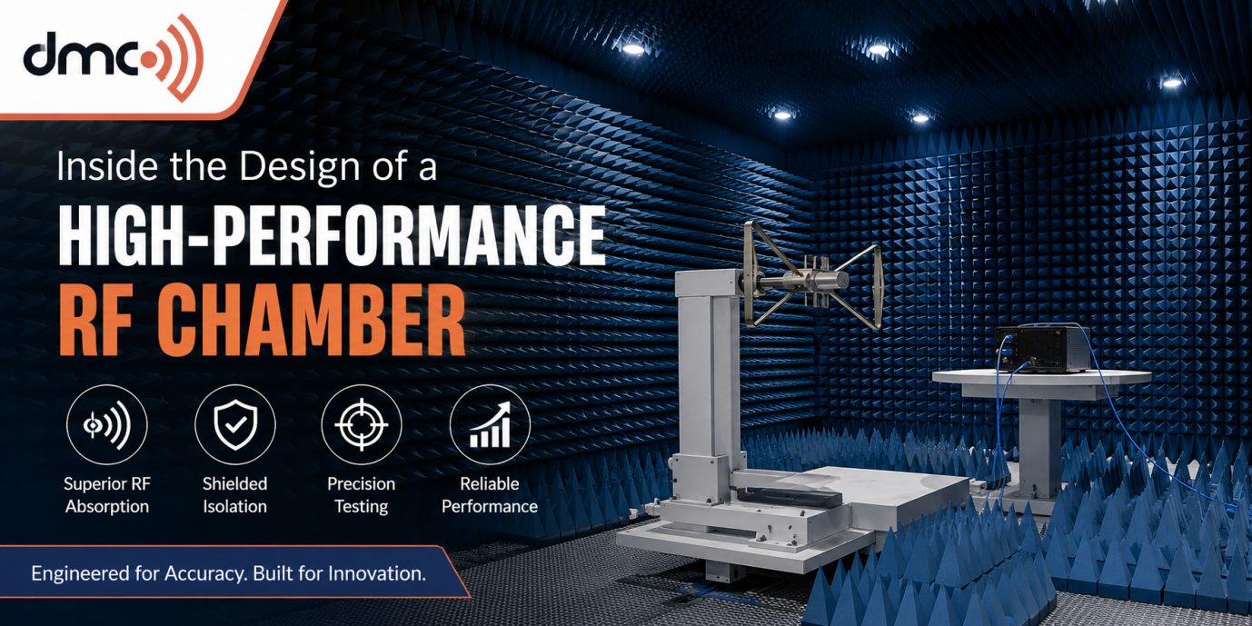
A high-performance RF chamber is more than a shielded room filled with absorbers. It is an intricately designed test chamber that controls electromagnetic energy, avoids unwanted reflections, prevents any kind of interference from the outside world, and creates consistent test conditions. Each and every element such as the shield itself, absorbers, doors, filters, ventilation, antennas, etc., could potentially affect the accuracy of tests.
Modern wireless, automotive, aerospace, telecommunications, and electronics industries increasingly depend on controlled RF environments. Tests like antenna characterization, over-the-air testing, electromagnetic compatibility testing, radar testing, and wireless devices development require a test chamber that will give consistent and predictable results.
A knowledge of the design of high-performance RF chamber can help in selecting the right design for specific tests.
1. RF Shielding – The First Line of Performance
The design process of an effective RF shielded room starts with the construction of its shielding system. The main objective is to ensure that the electromagnetic field created by this system will prevent any RF energy from leaving or entering the room.
A common shielding system comprises the use of metallic materials, such as steel. There should be no gaps or seams when assembling these panels.
The chamber design must also consider doors, cable penetrations, ventilation openings, power entry points, lighting, and other interfaces. These components require specialized RF treatment so they do not become weak points in the shielding enclosure.
In case of critical operations, one must evaluate the effectiveness of shielding for different frequencies and not assume that shielding will have the same performance at every frequency level.
2. Absorber Materials and Reflection Control
Shielding helps to ensure that any unnecessary RF energy does not enter or exit a room; however, simply shielding is not enough in order to make it anechoic. The issue of reflections inside the room must also be resolved.
This is when the RF absorber materials come in handy. These absorbers are placed on the inner surfaces of chambers such as walls and ceiling (and even floor) to minimize electromagnetic reflections.
Some of the RF absorber technologies are:
- Ferrite Tile Absorbers
- Pyramidal Foam Absorbers
- Hybrid Absorbers
- Special Low Frequency Absorbers
- Broadband High Frequency Absorbers
3. Controlling the Frequency Range
One of the most important design decisions is defining the operating frequency range before construction begins.
A chamber designed for lower frequencies can require substantially different absorber depth and treatment than a chamber primarily intended for higher-frequency wireless applications.
For example, an RF chamber used for antenna measurements may require broadband performance, while an OTA testing environment may be optimized around specific wireless frequency bands.
The engineer shall consider:
| Design Factor | Why It Matters |
|---|---|
| Frequency range | Determines shielding and absorber requirements |
| Chamber dimensions | Influences usable test volume and field behavior |
| Absorber type | Controls internal reflections |
| Shielding construction | Provides electromagnetic isolation |
| Door system | Maintains shielding continuity |
| Cable filtering | Prevents RF leakage through interfaces |
| Antenna position | Affects measurement geometry |
| Turntable/positioner | Enables repeatable device testing |
| Ventilation | Provides airflow without compromising shielding |
| Calibration | Confirms chamber performance |
Early specification of these requirements prevents costly redesigns later on.
4. Chamber Size and Test Volume
The physical dimensions of an RF testing chamber directly influence how a device can be tested.
The required chamber size depends on the equipment under test, antenna configuration, measurement distance, test methodology, and desired quiet zone. A chamber intended for compact electronics may have very different dimensions from one designed for automotive radar or large communication systems.
A high-performance chamber should provide sufficient test volume while avoiding unnecessary space that increases construction cost and absorber requirements.
The relationship between the source antenna, device under test, chamber boundaries, and absorbers should be evaluated during the design stage.
5. Antennas and Positioning Systems
In addition to other elements, antenna type and placement are necessary for the proper design of a test chamber. Depending on the purpose of a test chamber, different types of antennas may be utilized, such as broadband, horn, dipole, log periodic antennas, etc.
Positioners and turntables are also possible to be incorporated for controlled movements of the device under test. Automatic positioning increases reliability of measurements.
Positioning becomes particularly critical in the case of OTA testing since minor changes in positioning of the device under test may significantly affect the measurements.
6. RF Filters and Interfaces
Testing equipment usually requires electrical and RF interfaces, as well as power supply in the chamber. Each penetration into the chamber requires special engineering.
RF filters can help block the transmission of any unwanted electromagnetic energy via the power line. Filtered connectors as well as specific feedthrough assemblies are also useful for equipment interconnectivity without loss of chamber isolation.
The aim is to render the chamber usable without jeopardizing its electromagnetic qualities.
7. Ventilation without RF Leakage
A metallic box cannot just be thought of as another normal room. Testing instruments as well as the people handling them may generate heat, which requires ventilation.
However, the conventional ventilation system will result in RF leakage. Consequently, the high-end chambers have a sophisticated ventilation system, especially one that uses waveguide below cutoff or honeycomb structures.
8. Doors and Access Systems
The chamber door is another critical component. Even a small discontinuity around a door can affect shielding performance.
For the RF chamber door, conductive contact systems and well-designed seals are incorporated in their design. The type of door whether hinged, sliding, or other is determined by the size of the RF chamber, access needs, frequency range, and applications. For large test objects, consideration of the size and loading access of the door is critical.
9. Quiet Zone and Measurement Accuracy
A high-performance RF chamber should provide a sufficiently uniform and controlled region known as the quiet zone or test zone.
The condition of this area impacts the performance of the antenna, OTA test, radar test, and other radio frequency application. This includes reflections, multipath effects, absorption errors, and the shape of the chamber.
Validation of the chamber becomes very important after installation is completed. Tests may help to decide if the end product qualifies for the required electromagnetic properties.
10. EMC and RF applications:
Some of these can be:
- Antenna measurements
- OTA testing
- Wireless device testing
- Radar testing
- EMC testing
- EMI testing
- Automotive electronic equipment testing
- Aerospace and defense electronics testing
- 5G and next generation wireless technology development
An EMC chamber may have different design requirements compared to an antenna testing chamber, making it necessary to engineer for the specific application.
Tip For Pros:
Specify the full frequency band, test distance, size of the testing device, amount of test volume, method of measurement, and future needs before settling on a design of your RF chamber. If you do not consider these factors first, you can pay for additional costs of absorbers and dimensions that you will never need.
Why Professional Chamber Design Matters:
The performance of an RF chamber depends on the interaction of many systems rather than a single component. High-quality shielding cannot compensate for uncontrolled internal reflections, and excellent absorbers cannot correct a poorly designed shield interface.
Professional chamber engineering considers electromagnetic behavior, mechanical construction, ventilation, access, electrical interfaces, testing equipment, safety, and future maintenance together.
Such a way will help you build a well-designed RF chamber with high performance that is able to conduct stable measurements within the working range.
If your company plans to create a new testing lab with RF tests, the selection of the RF chamber will be an essential step to make.
Frequently Asked Questions
A high-performance RF chamber combines effective electromagnetic shielding with reflection control, appropriate absorber materials, controlled test geometry, filtered interfaces, and validated measurement performance.
RF absorbers reduce internal electromagnetic reflections, helping create a more controlled environment for antenna, OTA, radar, and wireless testing.
The operating frequency range affects shielding requirements, absorber selection, absorber thickness, antenna systems, chamber dimensions, and validation methods.
Yes, a properly engineered chamber can support multiple applications when its frequency range, test volume, antenna configuration, positioning equipment, and performance specifications are designed accordingly.
Validation confirms that the completed chamber performs according to its intended specifications and provides suitable electromagnetic conditions for reliable and repeatable measurements.