
Table of Contents
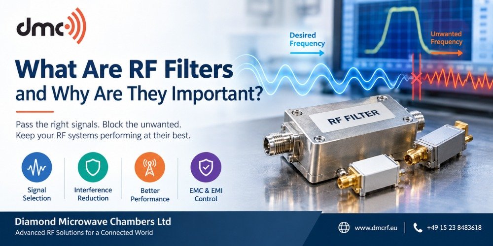
RF systems deal with a broad frequency range of signals, so it is vital to regulate the frequency range that should pass through a circuit. RF filters are special devices intended for selective transmission of certain frequencies and eliminating unnecessary signals, interference, and noise. These filters can be applied in wireless communications, radar equipment, satellites, antenna test equipment, RF labs, and many more.
For companies dealing with tough RF environments, it is important to have an insight into the behavior of their filters. Diamond Microwave Chambers Ltd provides the required support for RF and microwave testing needs where electromagnetic conditions play an important role.
What Is an RF Filter?
RF Filter is basically a frequency selective device that allows only certain frequencies to go through while blocking others. There are various factors that need to be considered when designing the RF filter and these include operating frequency, bandwidth, impedance, power, insertion loss, and rejection requirement.
There are basically four fundamental types of filters which are listed below:
Low pass filter: Allows low frequencies while blocking high frequencies.
High pass filter: Allows high frequencies while blocking low frequencies.
Band-pass filters: Permit a desired frequency band to pass while attenuating frequencies above and below that range.
Band-stop filters: Suppress a certain frequency band while passing other frequencies.
Such properties of RF filters make them very useful in dealing with a busy frequency spectrum and improving the quality of the signals utilized by the electronic equipment.
How RF Filters Work:
RF filters rely on the frequency dependence of electrical properties to achieve selective signal transmission. They may be implemented using conductors, capacitors, transmission lines, resonators, and other technologies.
On the most basic level, the filter sets up different impedance or responses to different frequencies. Wanted frequencies receive low attenuation, whereas unwanted frequencies will have more.
There are several parameters to describe the performance of an RF filter:
| Parameter | What It Indicates |
|---|---|
| Passband | Frequency range intended to pass |
| Stopband | Frequency range intended to be rejected |
| Insertion Loss | Signal loss introduced by the filter |
| Return Loss | How much signal is reflected back |
| Rejection | Degree of unwanted-frequency attenuation |
| Bandwidth | Width of the usable frequency range |
One parameter worth mentioning here is the insertion loss. It is critical to know the amount of insertion loss, as too much will reduce the wanted signal strength. The S-parameters are used in RF measurement systems.
Why is RF Filter Needed?
The modern electronic system usually works in an environment where there are several intentional and unintentional RF signals present. If proper filtering is not done, then such signals can cause interference in the receiver, measurements, communication link, or any other electronic circuit.
An RF filter may assist engineers in:
- Reducing any unnecessary out-of-band signals.
- Protect sensitive receiver inputs from strong interferers.
- Control harmonics and spurious emissions.
- Separate different frequency bands.
- Improve signal-to-interference performance
- Support EMC and EMI control strategies
- Maintain cleaner RF measurement conditions.
Filters are not a universal solution for every interference problem. EMC controls often use filtering and shielding together with grounding, cabling, and good system design.
Filters Used for Testing and EMC:
Testing using RF requires controlled signals that can be repeated. External electromagnetic interference can enter a test setup through cables, power lines, connectors, or other conductive paths. Properly selected filters can reduce unwanted conducted RF energy entering or leaving a system.
In shielded environments, filtering is especially useful at cable and power penetrations. The shield could protect against radiation of electromagnetic fields from penetrating into the enclosure, whereas filters could regulate unnecessary signals that propagate through conductors. Both mechanisms go hand-in-hand.
When considering the selection of the filter for an RF test facility, then the system should be considered as a whole, rather than taking into account the filter alone.
Selection of RF Filter:
When it comes to selecting a suitable RF filter, the first step is to define the real RF requirement.
Important considerations include:
- Operating and cutoff frequencies.
- Required passband and stopband.
- Required attenuation or rejection.
- Source and load impedance.
- Maximum RF power.
- Connector and mechanical requirements.
- Temperature and environmental conditions.
- Allowable insertion loss.
- Constraints of size and installation.
An RF filter that performs good rejection, but has high insertion loss, may not be applicable to the job. Also, an RF filter designed for certain impedance frequencies does not necessarily mean that it works the same way in a different circuit.
Pro tip:
RF filters should always be tested as part of the entire RF chain. Check its measured insertion loss, return loss, rejection, impedance, power handling, and frequency response under the conditions in which it will actually operate.
Role of Diamond Microwave Chambers Ltd:
Diamond Microwave Chambers Ltd specializes in RF and microwave test environments and related solutions. When RF filtering is applied in combination with proper shielding and controlled test conditions, the engineers will be able to devise more dependable methods for managing electromagnetic interference and RF measurements.
It all depends on the particular application, frequency range, measurement goals, and performance needed. Rather than choosing individual components on the basis of their nominal ratings, consider the entire RF system and the test environment.
RF filters are indispensable instruments for managing frequency contents in today’s RF and microwave systems. They assist in passing the desired signals, rejecting unwanted frequencies, and managing interference in order to ensure proper measurements and communications.
It is important to choose a suitable filter in consideration of frequency response, insertion loss, impedance, and the application, irrespective of the application in the receiver, transmitter, antenna, radar, wireless communication, or EMC testing environment. Proper RF filtering in combination with suitable shielding practices will help engineers create better electromagnetic environments.
Frequently Asked Questions
RF filters are frequency-selective devices that allow desired frequency ranges to pass while attenuating unwanted signals or frequency components.
The four basic types are low-pass, high-pass, band-pass, and band-stop filters.
They help control unwanted signals, reduce interference, manage harmonics, separate frequency bands, and support reliable RF system performance.
RF filters are used in communication equipment, radar, satellite systems, receivers, transmitters, antenna systems, RF laboratories, and EMC applications.
Common performance parameters include insertion loss, return loss, bandwidth, stopband rejection, and S-parameters such as S21.