
Table of Contents
- What Are Power Line Filters?
- There are two important types of interference to consider
- Key Advantages of Power Line Filters
- Choosing the Appropriate Power Line Filte
- The role of Diamond Microwave Chambers Ltd
In the design of electrical and electronic products, electromagnetic compatibility (EMC) plays a vital role. An electronic item has to perform as desired without generating EMI (electromagnetic interference) levels beyond the acceptable level, which can interfere with other equipment. There is a way to control EMI through the use of power line filters.
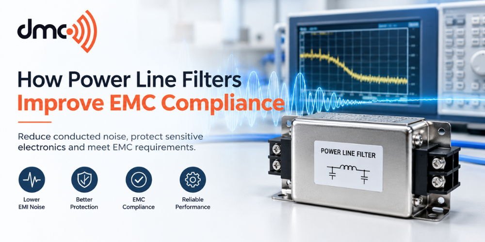
The term ‘power line filters’ denotes devices that are meant to filter out unwanted high-frequency electrical noise from AC or DC power lines. For manufacturers working toward EMC requirements, selecting and applying the correct filter can be an important part of an overall interference-control strategy.
What Are Power Line Filters?
The power line filter is the electrical circuit that is employed in between the power supply and the equipment. This is depending on the type of application since there are times when the filter will be using the capacitors, inductors, common mode choke, and resistors to reduce certain frequencies while passing the power frequency.
The filter cannot be used to replace the EMC design process but it acts alongside the other processes such as grounding, shielding, PCB design, etc.
These include:
- Industrial control devices
- Power supply and conversion devices
- Medical and laboratory devices
- Communication devices
- Automotive electronics
- Test and measuring devices
- Automation and manufacturing devices
How Power Line Filters Mitigate the EMC Problems:
The electronic devices may produce switching noise through the use of such devices as switching regulators, motor drivers, inverters, and digital circuits. Some of this noise can travel along power cables and enter other connected equipment.
A correctly selected power line filter provides impedance to unwanted high-frequency noise. The filter can therefore reduce conducted interference on the power connection.
There are two important types of interference to consider:
Common-mode noise: Noise that appears in the same direction on multiple conductors relative to ground or another reference.
Differential-mode noise: Noise that exists between power conductors, such as line-to-line or positive-to-negative interference.
Filter designs may address one or both modes. The exact performance is dependent upon the filter configuration, component selection, installation, impedance of source and load, frequency spectrum, and layout considerations.
Why It Is Important for EMC Requirements:
EMC standards may specify emissions requirements meant to restrict any disturbances caused by the equipment. For example, IEC 61000-6-3:2026 covers emission requirements for equipment used in residential locations when no applicable dedicated product or product-family standard exists. IEC 61000-6-4 covers generic emission requirements for industrial environments.
It is either conducted emission or radiated emission, depending on the specific standard and product classification.
The use of a power filter can assist in dealing with conducted emission, but for passing an EMC test, it is usually not enough to just add a filter. The whole equipment design and test arrangement are what ultimately determine the outcome.
Key Advantages of Power Line Filters:
| Benefit | How it Helps |
|---|---|
| Conducted noise reduction | Reduces unwanted high-frequency noise travelling through power connections |
| Improved system compatibility | Helps reduce interference between connected electrical equipment |
| Better EMC test performance | Can help control conducted emissions when correctly designed and installed |
| Protection from external noise | Can reduce the coupling of certain unwanted disturbances into equipment |
| Flexible implementation | Filters are available for different current, voltage, frequency, and installation requirements |
| Design support | Can complement shielding, grounding, PCB layout, and cable-management techniques |
Choosing the Appropriate Power Line Filter:
Choosing an appropriate power line filter should take into consideration the real electrical and EMC needs instead of picking the part with the greatest rated attenuation.
The key criteria include:
- Voltage rating: The filter should be able to handle the required system operating voltage.
- Current rating: Both continuous and operating current ratings need to be considered.
- Frequency: It is necessary to know where the problem of noise lies before the filter can be selected.
- Common-mode and differential-mode behavior: It is crucial to understand which of the two types of noise is causing trouble.
- Insertion loss: The attenuation at the necessary frequencies should be checked.
- Leakage current: It becomes particularly important in case of AC devices.
- Environmental conditions: Temperature, humidity, vibration and enclosures play their role in implementation.
- Physical aspects: Cable routing and filter mounting can have a big impact on performance.
Installation Can Be Just as Critical as Filter Selection:
A filter that would have otherwise been technically adequate may perform poorly when improperly installed. The filter-to-equipment connection should be made such that there is no unnecessary coupling of filtered and non-filtered conductors to each other.
When applicable, the designer should take into consideration:
- Separation of the noisy and filtered cable routes, where applicable.
- Minimization of unnecessary conductor lengths.
- Provision for proper bonding to the enclosure/reference plane.
- Following the manufacturer’s installation guidelines.
- Avoidance of installations that may allow the bypass of the filter by noise.
Testing the complete assembly and not just depending on the components’ specifications.
The filter’s performance may also vary between laboratory insertion loss testing and the actual installation since parasitic considerations and the system impedance effect the result. The manufacturer’s installation guidelines show that the filter’s performance can be affected by the installation.
Testing of Power Line Filters for EMC Compatibility
Testing will help to confirm that the chosen filter is actually solving the interference problem.Conducted-emission measurements can identify noise levels on power ports and show whether mitigation has improved the result.
A typical development process may involve:
- Frequency identification for EMC problem
- Dominant noise mode identification – Common Mode or Differential Mode
- Filter selection
- Installing the filter according to its application requirements.
- Repeating conducted-emission measurements.
- Assessing if any extra shielding, grounding, or re-layout is required.
To get accurate results, the testing process needs to be done according to the relevant EMC standard for that particular product or group of products. A general EMC standard is chosen if there is no particular standard available.
The role of Diamond Microwave Chambers Ltd:
Diamond Microwave Chambers Ltd operates in the EMC and RF testing industry providing solutions related to electromagnetic testing facilities. It is essential to have the right test environment for the development and testing of equipment.
The power line filters may be used as a part of EMC strategy, while test environments are needed by the engineers to assess whether the whole product meets the electromagnetic requirements.
Pro Tip:
Do not choose a power line filter just on the basis of its highest insertion loss value. First identify the problematic frequency range and noise mode, then consider voltage, current, leakage, safety, installation, and the impedance of the complete system. Validate the result through appropriate EMC testing.
Power line filters can play an important role in controlling conducted electromagnetic interference. The filters reduce noise at high frequency level in power connections and thus enable the engineers to develop an EMC design for conducted emission issues.
However, using the filters does not ensure that EMC compliance is achieved. An EMC design involves the use of the correct filter, grounding, shielding, PCB design, cable management, mechanical structure, and testing.
For the right results, it is important for the engineers to first determine the source of interference in order to pick the correct filter.
Frequently Asked Questions
Power line filters are electrical networks designed to reduce unwanted high-frequency electromagnetic noise travelling through AC or DC power connections.
They can attenuate conducted electromagnetic interference on power connections, helping equipment meet applicable conducted-emission requirements when properly selected and installed.
No. EMC compliance depends on the complete product design, applicable standards, test configuration, and other factors such as shielding, grounding, PCB layout, and cabling.
Important considerations include voltage, current, frequency range, common-mode and differential-mode attenuation, leakage current, safety requirements, environmental conditions, and installation method.
They are commonly used in industrial equipment, power supplies, automation systems, communication equipment, test equipment, medical electronics, and other electrical or electronic systems where conducted EMI needs to be controlled.