
Table of Contents
- Importance of Proper Installation of an RF Filter
- A good installation practice is to
- Common RF Filter Installation Mistakes
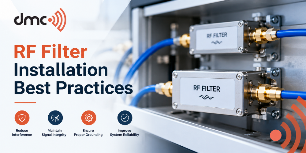
A correct installation is vital for obtaining satisfactory performance of RF filters in labs, industries, communication systems, and EMC testing conditions. Even the most advanced filter may not operate properly in case of improper installation, incorrect grounding, and inappropriate cables and joints use. Adherence to RF filter installation practices will allow minimizing undesirable EMI and ensure reliable system operation.
Diamond Microwave Chambers Ltd offers solutions for RF and EMC testing applications when efficient interference management is critical. Planning the installation of RF filters should take into account filter characteristics, electrical connections, grounding technique, enclosure, and working environment.
Importance of Proper Installation of an RF Filter
An RF filter is engineered to minimize the effect of interfering radio frequency signals, whereas letting the desired signals or power levels pass through it. The efficiency of a filter, apart from its electronic design, greatly relies on the way it is installed.
Inadequate installation of a filter may result in creating undesired interference paths. For instance, improper cable entry gaps, poor bonding, long cable lengths, or inappropriate grounding may diminish the efficacy of a filter.
Important installation considerations include:
- Selecting the correct RF filter for the required frequency range.
- Checking voltage, current, and power ratings before installation.
- Maintaining proper electrical bonding between the filter and enclosure.
- Keeping filtered and unfiltered wiring separated.
- Following the manufacturer’s installation instructions.
- Inspecting connections after installation and during maintenance.
1. Select the Correct RF Filter
The first step is choosing a filter that matches the application. RF filter selection should consider frequency range, insertion loss, current rating, voltage rating, impedance, connector type, and environmental requirements.
For power-entry applications, the filter must be suitable for the expected electrical load. For signal or communication lines, the filter should support the required signal characteristics without creating unacceptable attenuation or distortion.
2. Use Proper Grounding and Bonding
Grounding and bonding are particularly important in RF filter installation. A filter can lose effectiveness when the installation introduces a high-impedance path between the filter body and the surrounding shielded structure.
Where the design requires it, the filter should be bonded properly to the enclosure or reference structure using a suitable low-impedance connection. Paint, coatings, dirt, or mechanical gaps at bonding points can interfere with electrical continuity.
The exact grounding arrangement depends on the equipment design and applicable electrical and EMC requirements. Installation should therefore follow the filter manufacturer’s instructions and the system’s engineering requirements rather than relying on a single grounding method for every application.
3. Keep Filtered and Unfiltered Cables Separate
Cable routing is one of the most practical aspects of EMI filter installation. If filtered and unfiltered conductors run close together for long distances, unwanted coupling can allow interference to bypass the filtering arrangement.
A good installation practice is to:
- Keep input and output wiring physically separated.
- Minimize unnecessary cable length.
- Avoid routing filtered cables alongside noisy conductors.
- Use appropriate shielded cables where required.
- Prevent cables from creating unintended bypass routes around the filter.
This is especially important in shielded rooms and EMC test facilities where maintaining controlled electromagnetic conditions is critical.
4. Avoid RF Leakage Around Installation Points
A correctly specified filter cannot compensate for an installation that allows RF energy to bypass it. Openings, gaps, poorly fitted connectors, and unsuitable cable penetrations can become unintended paths for electromagnetic energy.
For shielded applications, filter mounting areas should be mechanically secure and electrically continuous where required. Any gaskets, mounting hardware, bulkhead connectors, or shielding components should be compatible with the system design.
Diamond Microwave Chambers Ltd considers these integration factors when supporting RF and EMC testing environments, because filtering performance is closely connected to the overall installation.
5. Inspect and Test After Installation
Testing should not be treated as the final formality. After an RF filter installation, connections, grounding, cable routing, and mechanical mounting should be inspected.
Depending on the application, appropriate verification may include electrical safety checks, continuity checks, insertion-loss measurements, isolation measurements, or EMC testing. The exact tests should be selected according to the equipment and applicable requirements.
Pro Tip:
Do not evaluate an RF filter only by its datasheet specifications. Check the complete installation, including mounting, bonding, cable routing, connectors, and potential bypass paths. A well-designed filter can only deliver its intended performance when the surrounding installation supports it.
Common RF Filter Installation Mistakes
Several avoidable mistakes can reduce filtering effectiveness.
- Choosing a filter without checking the required frequency range.
- Exceeding voltage or current ratings.
- Leaving gaps or poor bonding around shielded installations.
- Routing input and output cables too close together.
- Installing connectors or cables that create bypass paths.
- Failing to inspect the installation after maintenance or modification.
Avoiding these problems can improve reliability and make troubleshooting easier.
Following practical RF filter installation best practices is important for maintaining effective electromagnetic interference control. Correct filter selection, proper grounding and bonding, controlled cable routing, secure mounting, and appropriate post-installation testing all contribute to reliable performance.
For laboratories, EMC facilities, and RF testing environments, Diamond Microwave Chambers Ltd can support the broader requirements associated with controlled RF and electromagnetic testing environments. Selecting and installing the appropriate RF filters should always be based on the specific electrical, RF, safety, and EMC requirements of the application.
Frequently Asked Questions
Correct filter selection is fundamental, but installation quality is equally important. Frequency range, electrical ratings, grounding, bonding, cable routing, and mounting should all be considered.
Yes. Close or incorrect routing of filtered and unfiltered cables can create coupling paths that allow interference to bypass the intended filtering arrangement.
Proper bonding can help maintain electrical continuity between the filter and the surrounding structure. The appropriate grounding arrangement depends on the system design and manufacturer’s instructions.
Depending on the application, testing may include continuity checks, insertion-loss measurements, isolation measurements, electrical safety checks, and EMC verification.
No. The filter should be selected according to the required frequency range, voltage, current, impedance, insertion loss, connector configuration, environmental conditions, and application requirements.