
Table of Contents
- What Does Insertion Loss Mean in RF Filters
- How Is Insertion Loss of RF Filter Measured
- Factors that Influence Insertion Loss
- Comparison of Insertion Loss and Return Loss
RF Filters are key elements of communication, microwave, radar, EMC, and electronic testing equipment. They are supposed to be able to permit the right frequency to pass through while blocking any unnecessary signal. One of the critical parameters of RF filters that is often considered in the evaluation process is the insertion loss.
The Concept of Insertion Loss in RF Filters will help us understand the extent to which the power of the signal is decreased due to the filter placed into the RF signal path. For businesses dealing with high-frequency equipment, even a minor loss may be significant.
What Does Insertion Loss Mean in RF Filters?
The term insertion loss refers to the decrease in power of the signal due to the insertion of a component, for instance an RF filter, into the transmission line. It is typically given in dB.
In the case of real-world testing of an RF filter, insertion loss is usually assessed over the filter’s passband and indicates how well the required signal gets transmitted.
As a general rule, the smaller insertion loss figure corresponds to the higher percentage of the required signal being transmitted. Nevertheless, the parameter of insertion loss has to be analyzed together with other parameters such as return loss, passband ripple, bandwidth, and stopband rejection.
For instance, an RF filter could have good rejection outside of its required frequency range but low loss at its passband.
Why Is Insertion Loss Important?
It is clear that the insertion loss will influence the amount of usable RF power that can be achieved after a filter is used. If there are some passive components in the signal chain, their losses may increase system losses.
Some of the important reasons to control insertion loss include:
- Signal preservation: low insertion loss leads to better preservation of the RF signal within the passband.
- System requirements: high insertion loss leads to a decrease of the signal power that can be received by other RF components.
- Filter characteristics control: the measurement of insertion loss allows evaluating filter performance with respect to the specified frequency response.
- Filter design control: engineers can compare the characteristics of the actual filter with those of the theoretical one.
- Production control: consistent measurements will reveal differences between different filter models.
As Rohde & Schwarz states, the RF filter tests usually analyze such characteristics as S-parameters.
How Is Insertion Loss of RF Filter Measured?
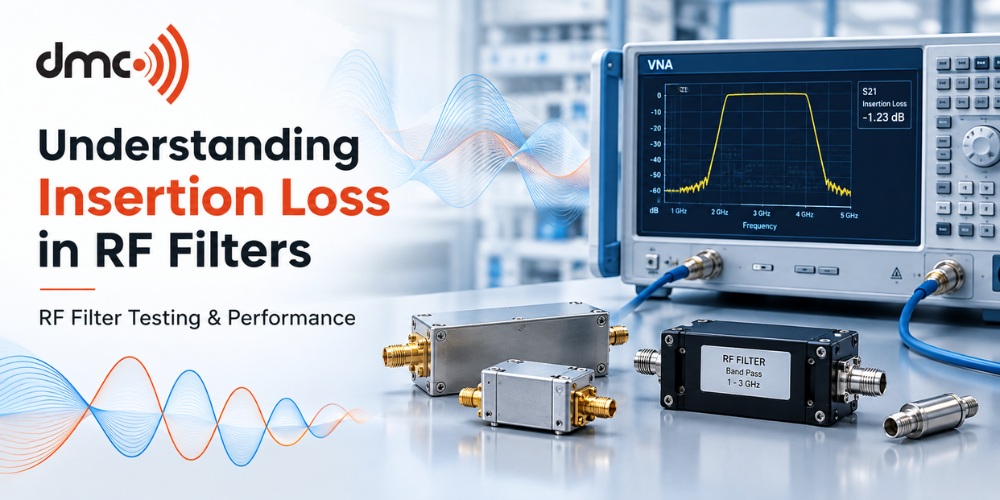
Vector network analyzer (VNA) is the common tool used for characterization of two-port RF circuits such as filters. VNA injects a known RF signal into the circuit and then measures reflection and transmission of the signal in the circuit. This results in S-parameters of the circuit.
When we talk about filters, one of the most important parameters is transmission parameter denoted by S21. The measured transmission response of the circuit can be used to find the insertion loss of the filter within the selected frequency range.
Common procedure is to:
- Set up the RF filter between the measurement ports.
- Calibrate the measurement setup for the desired frequency range.
- Define the frequency sweep settings and other measurement parameters.
- Make the transmission response of the filter.
- Analyze the insertion loss in the passband and other frequencies.
- Compare the measured response with the applicable specification.
Proper calibration is important because cables, connectors, and test fixtures can themselves introduce loss. Rohde & Schwarz describes through-calibration as a method for reducing the influence of test cables when measuring a filter’s transmission characteristics.
Factors that Influence Insertion Loss:
Insertion loss does not have to remain consistent at all frequencies. There could be some variation of the value depending upon the nature of the filter, the frequency of operation, impedance match, materials, construction, and setup for measurements.
| Factor | Effect on Filter Performance |
|---|---|
| Frequency | Insertion loss normally varies across the filter’s operating range |
| Filter design | Different filter topologies provide different passband and rejection characteristics |
| Component losses | Conductive and dielectric losses can contribute to attenuation |
| Impedance matching | Mismatch can increase reflections and influence transmission |
| Connectors and cables | Test-system losses can affect measured results |
| Temperature | Component properties can vary with operating conditions |
| Manufacturing variation | Physical tolerances can cause differences between units |
It implies that the insertion loss value should never be considered alone. The assessment should take into account the complete frequency response and conditions of measurement.
Comparison of Insertion Loss and Return Loss:
Insertion loss and return loss are two different measures of RF performance.
Insertion loss concerns the signal transmitted through a component, while return loss relates to the amount of signal reflected because of impedance mismatch. S-parameters provide a convenient way to analyze both transmitted and reflected RF energy.
A filter can therefore have acceptable insertion loss while still requiring careful attention to its input and output matching. Engineers normally review both transmission and reflection characteristics when evaluating an RF filter.
Applications of RF Filters:
- Wireless Communication Devices
- Test Equipment for RF & Microwaves
- Radar Systems
- Antenna Systems
- Aerospace and Satellite Electronics
- EMC/Interference Applications
- Industrial RF Equipment
- Measurement Equipment in the Laboratory
Each application requires a different kind of filter. The different kinds of filters that can be used include low-pass, high-pass, band-pass, and band-stop filters.
Selection and Evaluation of RF Filters:
In choosing an RF filter, engineers must consider more than just the insertion loss parameter. Factors like the necessary passband, rejection in the stopband, bandwidth, impedance, power handling capacity, and operating frequency must be considered among others.
Diamond Microwave Chambers Ltd is involved in offering solutions in the realm of RF and microwave technologies for testing and measurement applications. In evaluating the need for RF filters, the range of frequencies and measurement objectives are critical factors to start with.
Pro Tip:
While the loss may be very low in the center frequency of the filter’s passband, there can be more loss at the edges of the passband.
Insertion loss is one of the key specifications that can be used to define the degree of signal loss in an RF filter when it is inserted into the signal path. This specification is usually measured in decibels.
Correct measurements depend on the use of appropriate RF test equipment, calibration, connections, and well-defined test conditions. By taking into consideration insertion loss along with other factors such as return loss, bandwidth, and rejection, among others, one will be able to make a thorough evaluation of the performance of an RF filter.
Frequently Asked Questions
Insertion loss is the reduction in signal power caused when an RF filter is inserted into a transmission path. It is normally expressed in decibels (dB).
Lower insertion loss means less attenuation of the desired signal within the filter’s transmission range. It can therefore help preserve available signal power in an RF system.
RF filter insertion loss can commonly be measured with a Vector Network Analyzer (VNA) by measuring the filter’s transmission response, such as S21, across the required frequency range.
Frequency, filter design, impedance matching, conductive and dielectric losses, connectors, cables, test fixtures, temperature, and manufacturing tolerances can affect measured insertion loss.
No. Insertion loss describes the signal transmitted through a component, while return loss describes reflected signal caused by impedance mismatch. Both can be useful when evaluating an RF filter.