
Table of Contents
- Why RF Filters Matter in Industrial Systems
- Types of RF Filters
- Key Factors When Choosing an RF Filter
- Testing and Verification
- How Diamond Microwave Chambers Ltd Can Support RF Testing
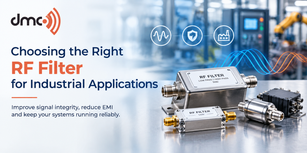
RF performance is becoming more critical for many industrial electronic devices. Industrial electronics from communication devices to automation systems, aerospace, defence, semiconductors, and wireless electronics can be affected by the presence of electromagnetic energy that should not be there. Choosing the correct RF filter for industrial electronics applications is one of the steps of RF and EMC design.
The RF filter allows passing the required frequencies and suppressing unwanted frequencies. RF filters are usually divided into the following types: low-pass, high-pass, band-pass and band-stop filters. The choice of an appropriate filter is dependent on many parameters: operating frequency, attenuation, impedance, signals’ characteristics and the surrounding environment.
For companies dealing with RF and EMC testing facilities, Diamond Microwave Chambers Ltd offers knowledge of many RF and microwave, EMC technologies like anechoic chambers, RF absorbers and antenna test systems.
Why RF Filters Matter in Industrial Systems
Electromagnetic energy can come from sources like switching power supplies, motors, digital electronics, and wireless transmitters, among others in industrial settings. Electromagnetic sources can generate noise that causes interference with circuits or communication channels.
The use of the correct filter will enable the suppression of unwanted frequencies while ensuring the passage of the desired frequency. The RF filter should not only consider the nominal frequency but rather the electrical and mechanical characteristics of the filter.
- Operating and unwanted frequency bands
- Required attenuation or rejection
- Passband insertion loss
- Characteristic impedance
- Signal or power level
- Environmental conditions
- Installation of physical nature
- Electromagnetic compatibility (EMC) considerations
One key factor in the evaluation of a filter is insertion loss since unwanted frequencies can be rejected while introducing loss within the desired signal. RF passive components are measured by parameters including insertion loss and return loss.
Types of RF Filters
The first step in choosing an RF filter is understanding what the circuit needs to pass or reject.
| Filter Type | Main Function | Typical Application |
|---|---|---|
| Low-Pass Filter | Passes lower frequencies and attenuates higher frequencies | Removing high-frequency noise |
| High-Pass Filter | Passes higher frequencies and attenuates lower frequencies | Blocking unwanted low-frequency components |
| Band-Pass Filter | Passes a defined frequency band | RF communication and receiver systems |
| Band-Stop Filter | Rejects a selected frequency range | Suppressing a known interference source |
The cutoff frequency separates the passband from the attenuation region, while the filter’s attenuation characteristics determine how strongly unwanted frequencies are suppressed.
Key Factors When Choosing an RF Filter
1. Identify the Required Frequency Range
Define the frequency which is needed to be transmitted/received by the system. Define the frequencies which need to be attenuated.
For instance, an RF receiver operating in a particular band of frequencies may need a band-pass filter to remove any out-of-band signals. A low-pass filter may be used in another system to reduce high-frequency noise.
Clear definition of the frequency helps avoid too much limitation of the filter.
2. Look for the Insertion Loss
The insertion loss shows the losses of signal when the filter is applied in the RF path. The lower insertion loss is preferable in the wanted frequency bands since the excess losses may decrease the available power of the signal.
However, the required value depends on the system itself, not on the filter parameters.
3. Pay Attention to the Impedance Matching
Most RF systems use standard values of the characteristic impedance which equals to 50 Ohms or 75 Ohms depending on the application. All components, cables and measuring instruments should be properly matched to minimize reflections.
The reflections and power losses may occur due to poor impedance matching; hence, the filter should have the appropriate impedance.
4. Determine the Required Attenuation
There is a need to reject interference sufficiently at these frequencies. Identification of these frequencies and amount of attenuation required is also essential. In case of EMC, it would be useful to conduct a measurement of the actual interference spectrum for selecting the right type of filter.
As per Rohde & Schwarz, measurement could assist in assessing the conducted emissions and improving the EMI filter performance.
5. Power and Environmental Considerations
The industrial filters may have to work in an environment with temperature variations, vibration, humidity, dust or high electrical loads. The component must be suitable to these conditions.
In high power cases, engineers must also take into account current, voltage, thermal and mechanical ratings apart from frequency.
RF Filter Selection Criteria
Prior to making a purchase or designing the RF filter, consider the following:
- The desired passband of the RF filter.
- The frequencies to be attenuated.
- The insertion loss.
- The required stopband rejection.
- The system impedance.
- Signal or power levels.
- The temperature and other environmental considerations.
- Connector and mounting considerations.
- The performance of the RF filter in terms of measurements.
- EMC or industry considerations.
Testing and Verification
Performance specifications for the filters should always be validated in practice in the actual system wherever possible. The filter which functions fine in the lab environment may behave differently when installed owing to parasitics such as cables, connections, PCB layout, grounding, etc.
For characterisation of RF passive components, S-parameter measurement is widely employed. For measuring various parameters such as S11 and S21, the vector network analyzer can be used.
In case of an EMC test, both conducted and radiated emissions tests will determine whether any interfering signals are suppressed. Pre-compliance testing during the design phase will identify issues before the compliance testing.
Pro Tip: Always consider the performance of RF filters not only within its operating frequency range but also insertion loss, attenuation, impedance, power-handling capability, and other characteristics at your frequency range of interest.
How Diamond Microwave Chambers Ltd Can Support RF Testing
Diamond Microwave Chambers Ltd is a company that is working in the RF & microwave testing industry using various technology like anechoic chambers, RF absorbers and antenna measurement systems used in defense, aerospace, space, satellite and semiconductor industries.
RF testing under controlled conditions can be of much use to engineers, especially when it is necessary to make repeatable measurements under minimum external interference of electromagnetic radiation and reflections. RF & EMC Chambers are designed to create controlled conditions for measurement.
Ideally, the RF filter will satisfy all needs of the system. Frequency response, attenuation, insertion loss, impedance, power handling, environmental and installation requirements should be taken into account at once. Thanks to proper RF measurement and choosing appropriate filters, industrial manufacturers will learn more about signal integrity and EMC.
Industrial companies developing and testing RF & microwave equipment can participate in a larger RF testing and measuring program, where Diamond Microwave Chambers Ltd can play its part.
Frequently Asked Questions
An RF filter is used to pass required frequencies while reducing unwanted frequency components. It can help manage interference and improve the performance of RF, communication and electronic systems.
The main types are low-pass, high-pass, band-pass and band-stop filters. Each type has a different frequency response and is selected according to the frequencies that need to be passed or attenuated.
Insertion loss indicates the signal loss introduced by the filter. Excessive insertion loss in the wanted frequency range can reduce available signal power, so it should be considered alongside the required filtering performance.
Impedance matching helps reduce reflections and unwanted power loss. Many RF systems use 50 Ω or 75 Ω characteristic impedance, depending on the application, so the filter should be compatible with the surrounding system.
RF filters can be characterised using measurements such as S-parameters. A vector network analyser can measure transmission and reflection characteristics, while EMC measurements can help evaluate interference reduction in the complete system.