
Table of Contents
Electronic devices have started operating in an environment where they face the presence of switching power supply, digital circuits, wireless transmission, motors, and other electromagnetic interferences. It is imperative to control such interferences as they affect the efficient performance of electronic equipment. Filters are among the various ways to control such interference, especially when it is coupled via wires.
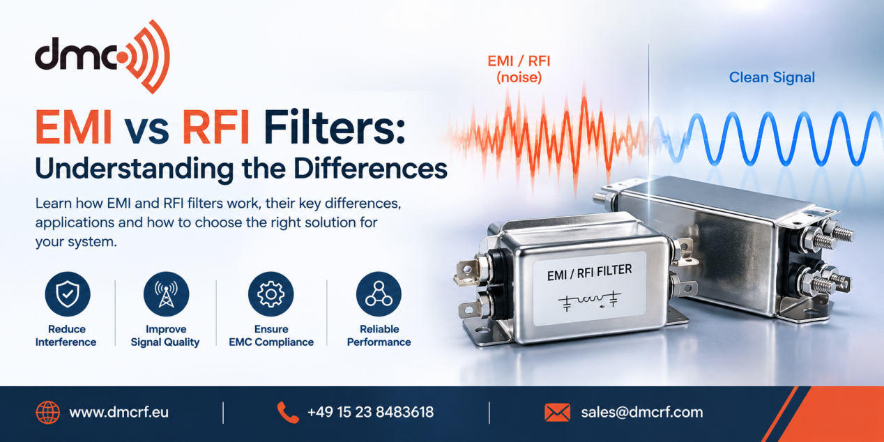
While the term EMI filter and RFI filter are often used as synonyms, their meanings do not remain identical. EMI (Electromagnetic Interference) is a general term which includes electromagnetic interferences that could be conducted or radiated.RFI (Radio-Frequency Interference) generally refers to interference associated with radio-frequency energy. Therefore, RFI can be considered a specific category within the wider EMI problem.
What Is an EMI Filter?
An EMI filter is an electronic device that reduces unwanted electromagnetic interference, while allowing necessary electrical power or signals to get through. EMI filters are commonly employed in power supplies, industrial devices, medical electronics, communications systems, automotive electronics, and laboratory test equipment.
Conducted EMI can propagate along power lines, signal cables, or any other conductive path. For example, switching power supplies may produce high-frequency interference which propagates back to the main power source. An appropriate input filter design will help reduce such interference, thus allowing equipment to comply with necessary conducted emission standards.
Common EMI filter components include:
- Capacitors to bypass the unwanted high-frequency noise.
- Conductors and common-mode choke coils to increase impedance to the unwanted current flow.
- LC or multistage filter networks to provide broader filtering range.
- Feed through capacitors for particular high-frequency applications.
- Ferrites to suppress high-frequency interference.
The correct filter depends on the noise frequency, current, voltage, source impedance, load characteristics, and required attenuation.
What Is an RFI Filter?
An RFI filter focuses on reducing unwanted radio-frequency interference. RFI can affect sensitive receivers, communication equipment, measurement instruments, wireless systems, and other electronic devices.
Because RF interference may occur over a wide frequency range, an RFI filter must be selected according to the frequency spectrum of the unwanted signal. A filter that performs well at one frequency range may not provide sufficient attenuation at another.
RFI can enter or leave equipment through conductive paths as well as through radiation and coupling. Consequently, filtering may need to be combined with shielding, grounding, proper cable routing, and enclosure design. Noise can couple through conductive, capacitive, inductive, or radiative mechanisms.
EMI Filters vs RFI Filters Differences:
| Feature | EMI Filter | RFI Filter |
|---|---|---|
| Meaning | Broad electromagnetic interference filtering | Filtering focused on radio-frequency interference |
| Typical concern | Conducted and/or radiated unwanted noise | RF-frequency unwanted signals |
| Applications | Power supplies, industrial electronics, EMC systems | Communication, RF, instrumentation, sensitive electronics |
| Frequency selection | Based on identified EMI spectrum | Based particularly on RF interference spectrum |
| Common components | Capacitors, inductors, chokes, ferrites | RF capacitors, inductors, ferrites, specialized networks |
| Main objective | Reduce unwanted electromagnetic disturbance | Reduce unwanted RF energy |
It is important not to take it for granted that filters for EMI will solve all problems associated with RFI. The efficiency of filters is determined by frequency, insertion loss, impedance, installation, and design.
Why Filter Selection Matters:
Selecting a filter only by its name can lead to poor results. Engineers should first identify the interference source and understand how the noise is travelling through the system.
A practical selection process includes:
- Define if the noise is conducted, radiated, or both.
- Define the frequency range of the noise.
- Identify if it is common-mode noise or differential-mode noise.
- Identify the system voltage and the maximum current the system can handle.
- Identify the specifications on insertion loss needed.
- Consider issues related to grounding and wiring.
- Try the filter in the real application environment.
Conducted Emission Troubleshooting:
Measurement on the equipment using a LISN could provide useful information on noise on power lines in the frequency domain. The obtained frequency spectrum could then be used to refine the filter design.
EMI/RFI Filters for EMC Testing:
EMC testing labs often have to deal with conducted and radiated interference. Filter can be of special importance in test labs where signals that get in via power or communication ports could affect the test results.
A properly designed test setup could incorporate filters along with RF shielding, absorbers, grounding, filtered power input system, and proper wiring management techniques working in concert, not as individual solutions.
Diamond Microwave Chambers Ltd provides testing facilities for RF and EMC where control of unwanted electromagnetic energy is an issue. The appropriate filtering approach should always be determined from the application’s electrical requirements and measured interference characteristics rather than from terminology alone.
Pro Tip:
Do not select an EMI or RFI filter based only on its advertised attenuation value. Check the attenuation curve across the actual problem frequency range, along with voltage, current, impedance, leakage-current, safety, and installation requirements. A filter can perform differently when installed in the final system compared with laboratory component-level measurements.
Concluding remarks:
There are two types of filters – EMI filters and RFI filters that are quite similar in terms of their nature but have different focuses. Conceptually, EMI is broader as opposed to RFI that refers to radio frequency interference. It is more vital to know about the cause, frequency, coupling and operational parameters of the interference than about its name from the filter label.
For successful EMI/RFI interference control it is vital to apply the following techniques: filtering, shielding, grounding, cables management, testing. Following a measurement-based approach would help you select the most efficient filtering techniques without interfering with the desired electrical or RF signals.
Any information on EMC or RF testing environments is welcome at Diamond Microwave Chambers Ltd.
Frequently Asked Questions
EMI is the broader category of electromagnetic interference, while RFI generally refers specifically to unwanted radio-frequency interference.
Yes, depending on its frequency response and design. An EMI filter can reduce RF noise when its attenuation characteristics cover the relevant interference frequencies.
EMI filters are widely used in power supplies, industrial equipment, medical electronics, automotive systems, communication equipment, and EMC test systems.
Identify the noise frequency, coupling mode, voltage, current, impedance, required attenuation, and installation conditions before selecting a filter.
No. EMC performance can also depend on shielding, grounding, PCB layout, cable routing, enclosure construction, and the specific interference path.